By Tommy H. Thomason

Thursday, December 27, 2012

Hellcats on CVEs

The CVE was an escort carrier built, in the beginning, on an oiler or merchant-ship hull. They had the smallest flight decks and slowest top speed of all the U.S. carriers. (See http://thanlont.blogspot.com/2012/12/making-it-harder-than-necessary.html) There were also far more of them commissioned during World War II than any other carrier type.

I had thought that during World War II they 1) only deployed "composite" squadrons and 2) never deployed with F6Fs. It turns out that I was wrong on both counts.

A composite squadron at the time, by the way, was called that because it operated more that one type of airplane, e.g. fighters as well as bombers. They came into being because the small number of airplanes that could be carried by an escort carrier didn't justify the bureaucracy associated with two or three squadrons, an air group commander, etc.

The FM-2 Wildcat was specifically developed for CVE-based VC squadrons. It was lighter and had a more powerful engine than the FM-1. The vertical fin and rudder were increased in size to compensate for the horsepower increase.
 National Archives 80-G-224669

Grumman did a design study in mid-1943 of an F6F-3 modified for operation from CVEs. The "F6F-4" was to be armed with four .50 caliber guns instead of six and have the 75-gallon fuselage fuel tank deleted; the "F6F EX. W.T." was to have a greater wing span. Each wing tip was to be extended two feet and the ailerons moved outboard, with the span increase being split between the ailerons and the flaps by seven inches and 17 inches respectively. The study concluded that the F6F was faster but the FM-2 was smaller and had a lower stall speed and better takeoff performance, making them more suitable for operation from a CVE.

As it turned out, there appear to be many instances of CVEs deploying with Hellcats.

Barnes (CVE-20) reportedly deployed with VF-1 flying F6F Hellcats in November and December 1943. Some of the results were ugly. The pilot was killed in this landing attempt during workups in October. (Note the very unusual variation on the tri-color scheme.)

National Archives 80-G-202611
This one wasn't fatal but still embarrassing for all concerned.

Some Sangamon-class CVEs deployments during World War II were with both a fighter squadron equipped with F6F Hellcats as well as a VT squadron assigned TBMs or a VC squadron operating SBDs and TBMs. The Sangamons (only four were built) were a bit longer and had a bigger hangar deck than the earlier U.S. Navy CVEs. The later Commencement Bay-class CVEs were similar in size and considered big enough and fast enough for Vought F4U Corsair and Grumman AF Guardian operation.

Sunday, December 23, 2012

And Now for Something Completely Different II

In April 1956, a VX-1 crew in a Sikorsky HSS-1 was conducting dipping sonar trials off Key West using Corporal (SS-346) as a target when cockpit instruments indicated that there was a problem with the main transmission. Since a transmission failure in flight was to be avoided at all costs, the pilot, CDR W.F. Culley, prepared to ditch while, I'm guessing, the sonar operator signaled the submarine to surface.

In any event, the submarine did surface and Culley quickly coordinated a plan with its skipper, LCDR E.O. Proctor, to save the helicopter by landing it on the deck aft of the conning tower. The ad hoc helipad was reportedly only two inches wider than the tread of the HSS-1's tires. It was unorthodox and risky but successfully accomplished with LTJG G.D. Ellis Jr out on deck serving as the first helo/submarine LSO.

National Archives 80-G-689826

Securely tied down, the HSS-1 was brought back to Key West and craned off.

National Archives 80-G-689827

Wednesday, December 19, 2012

Grumman A-6 Intruder History

The best history ever written on the A-6 Intruder is by Mark and Rick Morgan:


I'm going to go out on a limb here, since I haven't seen it yet, and say that the second-best book on the A-6 Intruder has just been released:
Note that it's by Rick Morgan who I rely on as a subject matter expert. It's available on Amazon and at a substantial discount.

Plus if you buy this book, you'll help convince a publisher to contract with Rick to do a similar work on the A-3 Skywarrior, which I for one would welcome, and a follow-on that covers the A-6s post-Vietnam.

Friday, December 14, 2012

Fitting In IV

The maximum folded span on a U.S. Navy carrier-based airplane and how it changed over time is obviously a subject of interest to me. See:
http://thanlont.blogspot.com/2009/07/fitting-in.html,
http://thanlont.blogspot.com/2010/07/fitting-in-ii.html,
and http://thanlont.blogspot.com/2010/07/fitting-in-iii.html.

To recap briefly, the 1949 XF3H mockup review report mentions a limit of 25' 4" due to the requirement for two airplanes to pass in the hanger. The span of what was to become the A4D was 25' when it was first laid out by R.G Smith. Based on the actual or proposed spans of some early 1950s single-seat jets, the limit was subsequently increased to about 27' 6".
One answer based on this 1948 Douglas proposal illustration is that it depends. Princeton was an early Essex-class carrier. The aircraft shown, an XF4D proposal, has a computed span when folded of 25' 9.5" based on the diagram (it was actually 25' 6"):
 Note that the clearance on the left side is only 18," whereas the other two clearance points are two feet apart, and that the clearance on the right is dependent on the height of the wing and then perhaps on the wheel base of the main landing gear. In other words, the limit for the folded span could vary somewhat based on the specific configuration of the airplane. Also, a subsequent ship alteration may have increased the width of this pinch point or resulted in the narrowest passage being someplace else on the hangar deck (fire-door openings didn't count). Another constraint as previously mentioned was the width of the elevator and the desire to move two aircraft up to the flight deck or down to the hangar deck at the same time.

Wednesday, December 12, 2012

Making It Harder Than Necessary?

Designing a carrier-based aircraft means dealing with several constraints that don't have to be addressed by designers of land-based ones. These affected folded size, weight, strength, takeoff and landing performance, etc. and varied by carrier class. However, in general, the designer was required to accommodate the most onerous. One across-the-board standard was the number that could be parted in the first 200 feet of an Essex-class carrier deck.

In the years following World War II, there were four basic U.S. aircraft carrier types:

Note that the elevators, deck width, and landing areas were roughly the same size. The major difference in size was total deck area with the escort carriers, CVEs, having the least. They were also much slower than the others, having a top speed of a bit less than 20 knots versus more than 30 for the bigger carriers including the CVLs.

The speed difference had a major impact on landing and takeoff performance requirements, since wind-over-deck was critical and the most that a CVE could generate in no-wind conditions was its own top speed. Because lift varies as the square of speed, that meant that the benefit of wind-over-deck in no-wind conditions was not about 30% less but more than 50% less.

In the early 1950s, due to budget and other considerations, only a few CVEs were deployable. However, many more were mothballed and available for recall if necessary. As a result, design requirements for new programs like the S2F and even the A4D jet attack airplane required operation from CVEs. Northrop proposed an early version of a lightweight fighter to the Navy in the early 1950s, without success, that was specifically focused on operation from CVEs.

Block Island was among the last of the escort carriers to deploy as such (some went to sea later as aircraft transports or communication relay platforms). Here CVE-106 is operating AF Guardians in the early 1950s as an ASW carrier.
It was put into reserve on 15 January 1954.

Having to deal with the lower wind-over-deck capability of the CVEs did provide naval aviators with extra margin when operating from the faster carrier classes. It also meant that the A4D Skyhawk could be successfully qualified to operate from former Royal Navy Colossus/Majestic-class aircraft carriers that had been modified with an angled deck, more powerful catapults, and stronger arresting gear like Melbourne, shown here alongside Kitty Hawk.

Monday, December 3, 2012

Having a Problem?

Somehow a string of what amounts to gibberish (to me, anyway) got inserted into the beginning of the text of "And Now for Something Completely Different". The only browser that couldn't seem to cope with it was Internet Explorer. I fixed it both here and on the most recent post in Tailhook Topics (http://tailspintopics.blogspot.com/2012/12/f-4s-wing.html). Since I don't have Explorer, if those of you who do and have a hang, please let me know with a comment on http://ththomepage.blogspot.com/.

Monday, November 26, 2012

Approach Lights Redux

It's surprising how often something new shows up for something old. I wrote about approach lights here: http://thanlont.blogspot.com/2012/04/night-carrier-landings-in-beginning.html

It was just brought to my attention that the F-4 had a green light on the left side of the fuselage that the LSO could use at night to determine roll attitude when he could not see the position light on the right wingtip, e.g. if the Phantom was turning left for lineup. It can be seen in this picture just below the crossbar in the A in NAVY. It looks like it is at the same waterline as the left-wingtip position light. I'm surprised that it is flush rather than protruding like a similar one is on the E-2.
The picture is cropped from a walkaround by Howard Mason of an F-4J on the Prime Portal website here: http://www.primeportal.net/hangar/howard_mason/f-4j_155563/

Friday, November 23, 2012

And Now for Something Completely Different

While doing research for my book on the development of U.S. Navy carrier-based jet fighters, I came across a cryptic reference to a proposed rocket-propelled interceptor.


I dismissed it out of hand although the Germans had not. In World War II, they developed the cannon-armed Me 163 interceptor that was rocket powered and had very high performance. One of the first aviation books that I remember reading as a preteen was Rocket Fighter by Mano Ziegler, a WW II Luftwaffe pilot who flew it.  Although legend has it that the Komet was more dangerous for its pilot than the B-17 crews that he was attacking, it was reportedly easy to fly and phenomenally fast for the time. The main problem was its fuel, C-Stoff (57% methanol/ 30% hydrazine/ 13% water), and oxidizer, T-Stoff (80% concentrated hydrogen peroxide / 20% oxoyquinoline. The combination was hypergolic, meaning it ignited just from being mixed, without the need for an ignition source. The Germans developed a process for safely fueling the Komet but a crash on takeoff or landing (particularly from the rough-and-ready fields available) was likely to result in an explosion or fire.

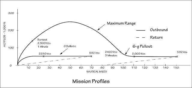
It turns out that the rocket-propelled interceptor proposal was a paper dated 8 June 1950 that was written by a U.S Navy officer, Commander Robert C. Truax, who was also literally a rocket scientist. It was a summary description and analysis promoting the development of a destroyer-based, rocket-powered interceptor.  In this case, furfuryl alcohol was the fuel and  nitric acid was the oxidizer. A small engine was provided for services and cruise;  a much larger one provided the thrust and control for vertical takeoff and acceleration.

In Truax's mission scenario, the interceptor would be launched vertically from the fantail of a picket ship, in this case a Gearing-class destroyer that would carry five of the aircraft.

After a flight profile measured in minutes, it would descend by parachute to the sea, from which it would be recovered to be prepared for its next mission.
 The range depended on the profile flown, ranging from zero ballistic (70 nm) to full ballistic (150 nm). Top speed was about Mach 4.
(Note that the full ballistic profile meant a recovery about 80 nautical miles from the launch point for a straight-out mission.)

An AN/APS-25 radar was to be used to locate and navigate toward the incoming bombers. 1,500 lbs of the 13,000 lbs gross weight was allocated to the weapons, which were yet to be defined. Aerial mines detonated by proximity fuses were one possibility.

In his paper, Truax noted that significant experience had been gained since the war with liquid-fuel rockets, including over 200 flights of the Bell X-1 with a rocket as its sole power plant. The Douglas D-558-2 was about to fly with a rocket engine. The smaller rocket engine in his design was one in development under contract to the Navy.

Although far-fetched, Truax's proposition received formal consideration at the Navy’s Bureau of Aeronautics and garnered at least one letter of support. However, even if the Korean War hadn’t become a distraction shortly thereafter, it seems very unlikely that the Navy would have taken any action on his rocket-powered interceptor after BuAer's review.

Truax retired from the Navy in 1959 as a Captain and went on to a career at Aerojet, after which he founded his own company, Truax Engineering. Among other things, he designed the Skycycle X-2 for Evel Knievel’s Grand Canyon jump. For more on Truax, see http://en.wikipedia.org/wiki/Robert_Truax .

Friday, November 9, 2012

F7U-1 Cutlass

My long overdue monograph on the F7U-1 Cutlass for Steve Ginter's Naval Fighters series is finally done and at the printer.

It is available from Amazon: http://www.amazon.com/dp/0984611479 , Sprue Brothers, Specialty Press, and Steve Ginter himself (http://www.ginterbooks.com/NAVAL/NAVAL.htm).

I guarantee that it has pictures and illustrations that you haven't seen before.

The F7U-1 was ahead of its time in many ways.
(Swept national insignia wasn't authorized until March 1955.)

Rogue markings were indicative of much more audacious decisions that resulted in F7U-1 development falling well behind schedule and the production program being terminated. I hope you agree that I've done its story justice.

Wednesday, November 7, 2012

Waving Them Aboard - The LSO

I did a very brief summary of Landing Signal Officer (LSO) history and responsibility here: http://thanlont.blogspot.com/2009/05/waving-them-aboard.html  This is an expanded discussion that is limited to landings on axial-deck carriers.

The LSO was a very early innovation in the development of aircraft carrier operations. He stood on a platform on the aft port side of the ship and visually coached the pilot of the approaching airplane into position for a successful landing or directed him to go around for another try.

According to legend, the first LSO was CDR Ken Whiting, the executive officer of Langley, the U.S. Navy's first aircraft carrier. He reportedly watched many of the first landings from what would become the LSO position and eventually grabbed two white sailor's hats to make his corrections more visible. Standardized signals and the creation of the LSO's paddles followed in short order.


To land on an axial deck carrier, the U.S. Navy pilots approached as for a short field landing, "dragging" the airplane in a speed just above stall and a constant altitude only about 20 to 30 feet (wheel height) above the deck. Upon receiving the "cut" signal from the LSO, the pilot closed the throttle, which resulted in an immediate descent onto the deck in the midst of the landing wires.

The pilot first had to get to the start of the "groove", which was where the LSO's coaching began. At the risk of oversimplifying, the groove began a few hundred yards (less for propeller-driven airplanes) behind the ship, where the pilot had completed his turn from his base leg and was lined up and on speed at approach altitude in level flight. At this point, the LSO's signals were visible and he began coaching the pilot as to height, airspeed, and line up in that order of priority. Those signals were advisory in nature relative to the two mandatory ones, which were the cut and the waveoff. Given the speed of the aircraft, there was only a few seconds for coaching and correcting before the LSO had to give the pilot either the cut or the waveoff signal. These were the basic signals:

There were several more, as illustrated in this article from Naval Aviation News in 1945:
Note that these were the "Day" signals. I haven't yet found a description of the corresponding "Night" signals.

The "slant" or "tighten turn" were used to coach the pilot as to line up, since—particularly with the F4U Corsair—the groove might well begin while the pilot was still turning to line up with the carrier. If the LSO thought that the pilot was in the process of making a good approach, he might therefore be given a Roger signal even while in the turn.

A wave off wasn't necessarily indicative of a poor approach. In order to bring all the airplanes in as quickly as possible, the interval between them left little margin for a problem getting one out of the landing area. A wave off might therefore result from a foul deck.
The LSO might also realize that the deck movement, which he could feel before the pilot could see it, was out of sync with the airplane's ability to settle into the landing area without being long (deck descending) or  touching down too hard (deck rising).

There were also variations in the LSO signals, possibly unofficial and specific to an Air Group. For example, these are the ones that Frank Bon used to wave AD Skyraiders in 1955:
Note the addition of the angling approach signal, which meant that the pilot was coming in at an angle to the axial deck rather than turning to line up with it. That may be the signal that this LSO is giving the pilot of the F9F Cougar during field landing practice or he may have stopped waving and commenced to relocate himself farther stage right. (The caption given with one instance of this picture's publication that he's giving a cut signal, which is clearly not the case.)

This is a good illustration of the cut signal:
Note that jets had to be cut farther out than the propeller-driven airplanes because they did not lose speed and settle as quickly:

The student LSO, who was invariably a Naval aviator, had to become well acquainted with what a good approach looked like, both in altitude and speed, from the LSO's viewpoint. With jets, angle of attack was the better indicator of the proper approach speed since the speed varied with weight (which could be significantly different due to the jet's much higher fuel burn) and the angle of attack did not. Early on, jets were marked with stripes, first on the nose and then on the vertical fin, to provide an angle of attack reference based on which stripe a certain part of the airplane, like the horizontal tail, was aligned with.
Getting the picture mean watching many landings waved by an experienced LSO. (The Brits also had the trainee LSO practice with experienced pilots who were unlikely to be misled by LSO judgment errors.) At first, the neophyte LSO would only be qualified to work with one type of aircraft. Over time, he might gain enough experience to bring other types aboard.

The paddles used were traditionally hand-made by the LSO himself. As a result, there was significant variation, for example round vs. square or oval.

The LSO initially wore the usual working uniform.

Whatever that might be.

When the higher speed of jets required that the LSO be visible from a greater distance, standard flight suits were modified to provided a more obvious indication of the relationship of the LSO's body and his arms.
 The requirement for all-weather and night landings increased the need for better visibility of the LSO. This was initially provided by a suit with stripes and paddles that fluoresced with black light but that was soon replaced with a lighted suit and paddles as shown here.

A readily available example of the activity on the LSO platform is provided by the excellent movie, Bridges at Toko-Ri.

Sunday, October 21, 2012

F8F Safety Tips—It Seemed Like a Good Idea at the Time

Much of this post was taken from Naval Fighter Number Eighty: Grumman F8F Bearcat, an excellent monograph on the Navy's last and arguably best propeller-driven fighter from the standpoint of air superiority.*

It is available directly from Steve Ginter (http://www.ginterbooks.com/NAVAL/NF80.htm), Sprue Brothers (http://store.spruebrothers.com/), or Amazon books.

In 1943, Grumman engineering was struggling to meet the weight goal for their new high-performance air-superiority fighter that was intended to replace the F6F Hellcat. In the process, they came up with a gimmick that would have been expected from their across-the-Sound rivals, Vought, but not from what was fondly referred to as the Grumman Iron Works.

The primary structural design requirement is specified as a limit load in gs at a design gross weight.  For fighters, the design gross weight was approximately the same as the combat weight, which was the operating weight (empty weight plus trapped fuel/oil, fixed armament, pilot, removable equipment, and other odds and ends) plus bullets and 60% of internal fuel. Application of the limit load was not to result in a permanent deformation of the structure. There was also an ultimate load requirement, which was expressed as a percentage of limit load, below which the structure might be permanently bent but would not break. If it was subjected to something greater than ultimate load the designer was no longer responsible for what happened.

At the time, according to Corky Meyer,  a longtime Grumman test pilot and one of the coauthors of the monograph, the limit load requirement was 7.5 gs and the ultimate load almost twice that, 13 gs. To minimize weight, the Grumman innovation was to have the outboard three feet of the wing, including that portion of the aileron, break off at 9 gs, which would allow the remaining, less-leveraged wing structure to sustain an ultimate load of 13 gs. The weight savings was 230 lbs, a significant reduction for an airplane with an empty weight of only 7,600 lbs.

The weak link, so to speak, was just outboard of middle hinge of the aileron so adequate roll control would still be available in the event that both tips broke off, which was the expectation. The concept was successfully tested in flight using an F4F Wildcat modified with breakaway wingtips. F8F flight tests were subsequently accomplished by Corky himself to include landings with only one wingtip broken off to demonstrate controllablity in the asymmetric condition. Demonstrated and proven, the safety tip was standard on production Bearcats.
It also worked in service, with pilots even landing on carriers after they had parted company with their wingtips by overloading their airplanes. "I made a wide gentle pass—had 100 knots at the 90-degree point. The pass felt very little different, just a little fast. The landing was normal with quite a bit more shock on catching the wire."

There were, however, fatal crashes associated with the breakaway of only one wingtip. One was a Blue Angel who failed to pull out of the downward finish to a Cuban 8 at an airshow in September 1946. Another was during pullout from a dive-bombing run. The resulting sudden roll reduced the effectiveness of a pullout to less than that needed to avoid hitting the ground.** That only one wingtip came off instead of both was ascribed to variation in manufacturing tolerance (size of rivet holes, clamp-up load, skin thickness, etc) in the structure and a difference in the weakening over time of the weak-link structure in each wing caused by carrier landings and buffet during high-g maneuvers.

The response was to add a ballistic backup to the weak link to insure that both tips came off at the same time. Primacord (a thin plastic tube filled with explosive) and a microswitch were added to the break point and the installations on each wing were connected electrically. If the microswitch opened on one wing, indicating that the wingtip had separated, a circuit would close to detonate the Primacord on the other wing, insuring that its wingtip separated as well.  Corky demonstrated the removal of one wingtip ballistically in flight.

If there was understandable nervousness about bombs embedded in aircraft structure, it wasn't enough to insure that adequate safety measures were established or observed although the installation was identified with a red line on at least some Bearcats.
 Capt Paul Anderson collection via Jan van Waarde

It was therefore probably inevitable that a short circuit during maintenance on an F8F caused the wing tip to separate, killing a sailor. According to the Flight Manual "it has not been possible to make and maintain a continuously reliable installation of the explosive wing-tip-shedding device in service airplanes." The result was an airframe change in early 1949 to delete the Primacord installation and eliminate the weak link with a structural beef-up of the wing.

* A somewhat different story of the genesis of the Bearcat than the one provided by Corky in his monograph can be read here: http://thanlont.blogspot.com/2011/02/conception-of-f8f-bearcat.html

** Contrary to what you might think, the loss of lift from the wing tip was usually accompanied by a net increase in lift from the rest of the wing rather than a decrease. The nose-down pitching moment of the wing was reduced by the loss of the wing area but the nose-up pitching moment of the horizontal tail remained the same, resulting in an increase in the angle of attack of the wing at the amount of aft stick when the tips came off. If the increase didn't exceed the angle of attack for stall, lift would therefore increase.

Friday, October 5, 2012

Westinghouse Redux

All this time, I had misidentified the jet engine under the F4U at Patuxent River in 1944 as the Westinghouse 9.5-inch engine instead of its original 19-inch Yankee engine. I'm not sure why I didn't compare it more closely to the airplane's tires to establish its diameter. However, it's clear to me now that it was the bigger Yankee engine so I've revised the post accordingly: http://thanlont.blogspot.com/2011/03/from-hero-to-zero.html

Thursday, September 6, 2012

Baby Steps for the Tip of the Spear

One of the U.S. Navy's first airplanes was a swept-wing biplane with no horizontal tail. Burgess was a U.S. shipbuilding company that got into the airplane business in 1910. Beginning with Curtiss and Wright designs, it built airplanes under license for several years. It also bought a manufacturing license for the Dunne D.8 that was developed by John Dunne in England. The Navy bought at least a few as the Burgess-Dunne AH-7 in 1914.
NA 80-G-452496

The sweep of the wing was obviously not for speed but to move the pitch control surface far enough aft of the center of gravity to provide sufficient pitching moment for control of angle of attack.

At least one was fitted with bomb racks, one under each wing as evidenced in this picture taken at Pensacola in September 1916.
 NA 80-G-463263

The bomb looks almost home made...


Thursday, August 30, 2012

Halcyon Days IV

In the summer of 1951 when this picture was taken by VF-51 squadron mate John Moore, Neil Armstrong was not yet 21 and had just been promoted to Ensign.  Air Group Five, of which VF-51 was a part, had just deployed on Essex and they were enjoying a day at the beach in Hawaii on their way to the Korean War.

Armstrong had completed four semesters of college at Purdue University, financed by the Navy under the Holloway Plan that obligated him to three years of service at that point before completing his degree. He was designated a Naval Aviator in August 1950, two weeks after his 20th birthday and two months after the start of the Korean War. Although still only a Midshipman, he had the good fortune to be assigned to VF-51 in November. The squadron was in the process of reforming with new personnel and equipment following a deployment on Valley Forge. Although jet transition units had been established to check out pilots, Neil's first flight in a jet was solo in a VF-51 F9F-2B Panther on 5 January 1951. (The Navy was more casual about training then and yet to realize that more rigor was necessary to avoid a horrendous loss of pilots and airplanes.)

Here, Midshipman Armstrong is flying F9F-2B number 116 as the wing man of Lt(jg) Ernie Russell in 107. John Moore took the picture.

Air Group Five deployed aboard Essex on 26 June 1951. The picture of young Armstrong at the beach was taken during final workups in July in Hawaii. On 29 August, little more than a year after becoming a Naval Aviator, he flew his first combat mission. Less than a week later, a cable strung between two hills as a crude antiaircraft booby trap cut off six feet of one of his wings. He managed to herd the badly damaged jet out over the water where he could eject without much risk of capture. He went on to fly a total of 78 combat missions.

Armstrong left the active Navy in the fall of 1952—although he  continued to fly in the Naval Reserve through late 1960—and returned to Purdue. He graduated with a bachelor's degree in Aeronautical Engineering and joined NACA. It was a most satisfactory beginning to a storied career.

Thanks to the staff at the Emil Buehler Library at the National Naval Aviation Museum for the pictures. Many of the facts included above were taken from First Man: The Life of Neil A. Armstrong by James R. Hansen.

Sunday, August 5, 2012

Halcyon Days III

I'm not sure yet when this photo was taken but it is probably late 1955 or early 1956. The aircraft are all newly assigned to NATC for test and evaluation before being declared suitable for service use. Leading the echelon is an Douglas A3D-1 Skywarrior that was to be participate in at-sea carrier trials in June 1956 aboard Forrestal. The change from the overall blue to the gray/white scheme had just been decreed in February 1955, which is why its folding fin, rudder, folding wing sections, flaps, and ailerons are blue.

The two new all-weather fighters were the McDonnell F3H Demon that is next in the formation with a Douglas F4D Skyray below it. These are finally about to get to the fleet, having been in development since first flights in 1951. Both were delayed by the J40 engine fiasco (as was the A3D, but it had an earlier start) that required an engine substitution. The A3D and the F4D were subsequently powered by the P&W J57 while the F3H had to make do with the Allison J71.

The last three are all powered by the Wright J65 engine. From top to bottom, they are the North American FJ-4 Fury, Grumman F11F-1 Tiger, and Douglas A4D-1 Skyhawk. None of these three (or the F4D for that matter) were selected for development after a formal competition. The FJ-4 and the F11F (as the F9F-8 and then F9F-9) were initiated with budget designated for product improvement of a production airplane, the FJ-3 and F9F-6 respectively. The A4D rose from the ashes of the A2D program and was the beneficiary of its budget. (Before McNamara, the services had a lot more flexibility in airplane development.)

Most of the six were not as successful as hoped. The FJ-4 and the F11F were what the fighter class-desk officer at the time believed to be most appropriate for a day fighter: light, small, simple (inexpensive), maneuverable. The FJ-4 didn't even have an afterburner although Grumman had the foresight to add one to its F11F. As a result, the F8U, which was won a true competition against a specification that emphasized speed, almost literally blew them away. The FJ-4 fighter was relegated to the Marine Corps; the Navy subsequently bought some FJ-4Bs as an attack aircraft to give Ed Heinemann something to think about during early A4D development and production when it felt that Douglas wasn't being responsive to its concerns.

The F4D never got an armament capability that made it an effective all-weather aircraft. Although it deployed several times, it was really not suited for defending the carrier if the skies were cloudy. The Marine Corps operated it longer and didn't mind its shortcomings. The F3H wound up armed with the Sparrow missile, so it had a true all-weather capability. It also begat the McDonnell F4H Phantom and that alone justified its existence.

As for the big A3D and the little A4D, they both enjoyed long and honored careers, the A3D in part because it was big and the A4D, because it was little...

Tuesday, July 24, 2012

The Vought F5U: Missed it by that much...

Once upon a time, NACA engineer Charles Zimmerman postulated that a very low-aspect-ratio wing would provide low-speed lift and short takeoff and landing performance. The wing ultimately became a disc with large propellers mounted at the forward outboard edges and rotating in opposite directions to the wingtip vortices. These made the wing even more effective at low speeds and increased the effective aspect ratio for cruise. Wind tunnel testing established the feasibility of the concept. Zimmerman joined Vought in 1937 where he designed and flew a model that demonstrated the configuration's potential for very low speed flight. Vought proposed a concept demonstrator, its V-173, to the Navy, which was intrigued enough to provide Vought with a contract for one in May 1940.

The V-173 was not small but fortunately it was light, a wooden and metal frame covered by fabric, since it was only powered by two 80-hp Continental engines.
Its first flight was on 23 November 1942. It was almost its last, since Boone Guyton found it difficult to get it turned back around to return for landing. Control modifications were made before its next flight that provided better handling qualities.

The Navy had already ordered a production version, the F5U. It was exactly the same size as the V-173, but of all-metal construction and powered by two 1,350-hp P&W R-2000 engines.

The mockup had three-bladed propellers but it was soon apparent to the engineers that the installed power and necessary rotor-hub gimbal (the blades had to "flap" to relieve root bending loads) dictated a design with four blades.


The development of the propellers and qualification of the gearboxes that interconnected the engines and the propellers delayed the program. It may have made its first low-power ground runs with F4U propellers. (The left-hand one appears to have the propeller blades rotated 180 degrees in the hub.)

The F5U's propellers had a much larger root chord and the opposed blades were paired. Note that the blade pairs were also staggered fore and aft.

The F5U was finally ready to fly in March 1947 but by then it was apparent that new fighters would be jet propelled. Although the F5U reportedly made short hops down the runway at Sikorsky Field, a first flight was not accomplished before the Navy terminated the program and directed that the prototype be destroyed.

Fortunately for aviation enthusiasts, Vought donated the V-173 to the Smithsonian. It languished at the Silver Hill storage facility for many years before being shipped to Grand Prairie, Texas where Vought Heritage volunteers restored it to like-new condition. It is now on display at the Frontiers of Flight Museum in Dallas, Texas. See http://www.flightmuseum.com/